|
|
| |
|
|
| |
Ross Compressor
The Ross Compressor has long been admired as one of the finest compressors produced. Accordingly, it
is also one of the most copied, cloned, and modified compressors out there. Two of the most notable clones of the Ross
are the Keeley Compressor and the Analogman CompROSSor. The Way Huge Saffron Squeeze is reportedly a modified version of
the Ross Comp. also. But like all electronics designs, there is some room for improvement. In the schematic of the Ross
Compressor below, you'll see some parts that are highlighted in blue. These parts were added
by the R.G. Keen to help improve the performance of the circuit.
The 1M resistor on the input of the circuit is there to help prevent popping when using true bypass switching with either
a DPDT switch or a 3PDT switch. This popping is caused by voltage leaking from the input capacitor, and finding its way
onto the switch. When you activate the switch by stomping on it, the sudden voltage shift from one set of contacts to the
other causes the "true bypass pop," which is sometimes quite loud. By adding the 1M resistor to the input, the voltage
leaking from the input capacitor is pulled off to ground so it doesn't get to the switch. The two new capacitors are there
to help filter the voltage going to the circuit to ensure low noise operation. The 1µF capacitor filters the bias voltage, or
Vb, and the 10µF capacitor filters the main voltage coming from the battery or DC adapter. The 10µF capacitor could be cranked
up to 47µF, but it probably wouldn't make much of a sonic difference. Another change that I made to the circuit, highlighted
in green on the schematic, was to reduce the 220pF on the input to ground to 100pF. This prevents
too many highs from being removed.
For my Ross Compressor project, I inquired about further modifications over at Aron's Stompbox Forum
and was helped by Mark Hammer, who has a great deal of knowledge when it comes
to circuits such as this. Mark suggested a way of adding a SPDT On-Off-On toggle switch and a couple of extra resistors so that the
player has the ability to alter the recovery time...fast/medium/slow...depending on the position of the switch. Another mod that was suggested by Mark to
keep the Compressor from muddying up the tone is to place a 0.001µF capacitor in parallel with the 10K output resistor. This allows some more treble to make its way
to the output, brightening up the tone so that it's very close to the bypassed tone. I used a socket for this capacitor in case I want to adjust the amount of treble
in the future. In schematic below the "Hammer" mods are highlighted in red. Below is the description of the mods that were posted by
Mark Hammer:
|
|
"If you use a 3-position on-off-on SPDT toggle for this, then the sensible way to wire it up is as follows.
- Replace the 150k resistor on the board with a 10k+150k pair in series, installed like a "St. Louis arch" with their junction pointing
up; be sure to leave a little extra lead from the 150k resistor sticking out on the component side of the board, which you'll
need for the other steps below.
- Run a lead from the junction of the 150k+10k pair to the common (centre lug) on the switch.
- Run a lead from the other end of the 150k resistor to one of the outside lugs on the switch.
- Solder a 39k resistor from the unused lug of the toggle to the other *outside* lug.
Done.
When the switch is in the centre position, it isn't connected to anything, so the effective resistance is the sum
of the 150k and 10k resistors, or 160k. When the switch is in the side position where it connects directly to the
other wire going to the board, it shunts the 150k resistor, making the effective resistance 10k. When it is switched
to the other side position, you have a 39k resistance placed in parallel with the 150k resistor, yielding a combined
parallel resistance of 30.9k, which yields around 40k when summed with the 10k in series.
Voila, a simple and easy fast/medium/slow recovery control with very little modification to the board, a small
footprint for installation into smaller enclosures, lower cost than a pot+knob, easily repeatable settings, and
meaningful differences in settings.
Where you will notice the difference in settings will be when you try to play faster, while still maintaining pick
attack. The stock setting yields nice long sustain/compression, but at the cost of not being able to respond to new
notes with any rapidity. The upshot is that you may not be able to hear the difference until you start trying to pick
differently. To the best of my knowledge, there is no impact on any of the other tonal characteristics of the pedal,
although if you feed it a noisy signal the faster recovery will mean that the input hiss comes back to you sooner."
|
|
"In general, simple, single-channel, full-bandwidth compressors of this type have the effect of creating the illusion of
treble being attenuated (just as they create the *illusion* that the instument sustains better/longer). There would seem
to be two or three paths towards improving that. One is to compress less. Another is to mix in a bit of uncompressed treble
with the compressed signal. Another is to reshape the frequency response of the fully compressed signal.
Although there are probably better ways to do it, I sent in an Orange Squeezer mod to JD Sleep for posting on generalguitargadgets
that attempts to accomplish option 3. It uses a simple bypass cap on the volume control that lets more treble through, relative
to bass, as you turn the volume down. If you look at the Dyna/Ross schem (and bunch of other oddly enough), you'll see that the
output path consists of a 0.05µF cap. a 10K fixed resistor, and a 50K pot. That 10K resistor is a mystery to me as to why its there,
but lets just count our blessings and not ask too many questions.
How is the 10K resistor a blessing? Because it allows you to stick in a bypass cap. Note that the 10K+50K arrangement behaves as if
it is a 60K pot that can never be turned up ALL the way. If a bypass cap could work on a 50K pot, why couldn't it work on a 60K pot?
The nice thing here is that the treble boost it provides is applied across the entire range of volume-pot settings. Try a 1500pF (0.0015µF)
cap in parallel with the 10K resistor for starters. If my assumptions and math are right, that should give a slight advantage to content
above 2200hz in your output signal. That may or may not be enough to do the trick for you."
|
|
Below is a schematic of the modified Ross Compressor that I built, complete with R.G. Keen and Mark Hammer mods:
I made some changes in my project which makes the parts selection different than the TonePad layout that I used to
build my version. First off, I used a 500K REVERSE audio taper pot for "sustain" instead of the 500K linear taper pot that's listed. The reverse
audio pot gives a much improved "feel" to the sustain control. The second change I made was using 2N5088 transistors instead of the 2N3904 that are
listed on the TonePad layout. The 2N5088s are higher gain than the original 2SC1849 transistors, which are around 200-250, and they're also lower noise.
At any rate, I would use either 2N4401 or 2N5088. I've heard of some builders using the 2N4401 with good, low noise results. My third change was to
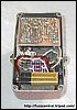
use all 1% metal film resistors, which are known to be less noisy than 5% carbon films and certainly carbon comps. Take a look at the guts of a real
Ross Compressor:
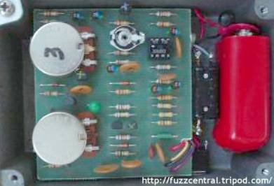
In the picture you can see at least two of the reasons for the noise level of the original pedal...carbon film resistors and ceramic disc capacitors.
The polarized capacitors in the circuit are tantalum...not a bad choice since they do have a longer life span than common
electrolytics, but they do cost quite a bit more than electros. The tantalums probably won't make enough of a difference
for even the most staunch "audiophile" to pick out. Also notice that the circuit doesn't have true bypass, but uses what
appears to be a Carling SPDT switch. I like the nifty red "sock" around the battery, though.
|
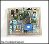
Below are some pictures of my modified Ross Compressor. Click the thumbnail for a full-sized image! Use your browser's
"Back" button to return to this page.
|
|
|
|
|
Here are some voltage readings from my Ross Compressor Clone, with the 2K trimpot already tuned
according to the TonePad instructions, the SPDT switch in its center position (160K), and the "sustain" control
turned all the way down (counter-clockwise).
IC1 (CA3080E)
|
Pin 1 = N/U*
|
Pin 2 = 4.92V
|
Pin 3 = 4.91V
|
Pin 4 = 0V
|
Pin 5 = 0.633V
|
Pin 6 = 2.76V
|
Pin 7 = 9.5V
|
Pin 8 = N/U*
|
*N/U = Not Used (not connected to anything)
|
Q1 (2N5088)
|
Q2 (2N5088)
|
Q3 (2N5088)
|
Q4 (2N5088)
|
Q5 (2N5088)
|
C
|
7.98V
|
C
|
7.28V
|
C
|
9.5V
|
C
|
9.5V
|
C
|
9.5V
|
B
|
2.10V
|
B
|
2.87V
|
B
|
0V
|
B
|
0V
|
B
|
9.32V
|
E
|
1.65V
|
E
|
2.34V
|
E
|
0V
|
E
|
0V
|
E
|
9.0V
|
|
Ross Compressor PCB and Layout
|
Tonepad
|
Ross Compressor Parts List
|
Here
|
Build Difficulty: Moderate
|

|
|
The PCB and Layout are located at TonePad and were drawn by Francisco Peña. The PCB will require some
modification to accomodate the extra mods suggested by Mark Hammer. If I obtain permission from FP, I could post the modified
PCB and Layout here for download.
|
|
|
| |
|
|
|


