|
|
| |
|
|
| |
Tycobrahe Octavia
Few pedals carry the same legendary status as the Tycobrahe Octavia. It's quite possibly one of the
hardest to find pedals around, mainly because there weren't a lot of them built. When you do find one, the price can very
easily surpass $800 for a good one. There are a lot of stories surrounding this pedal as to whether or not it's the same
circuit that was used by Jimi Hendrix. The story is that the circuit was designed by Roger Mayer to be used by Hendrix and
was copied by one of the Tycobrahe engineers when it was brought in for servicing in the US. Do I believe it? Not really.
Roger Mayer also claims that the circuit that was copied was actually meant to run off higher voltage, around 24 volts DC.
This is a possibility and it may give the pedal a more tame personality. But, for what it's worth, I like the Tycobrahe
Octavia just the way it is...loud and aggressive! This circuit has a truckload of distortion right off the bat, and also
has some crazy swells that add a lot of animation to the sound. The schematic below is the only example that I know of that
has the correct original transistor part numbers, and also note that the capacitor on the third lug of the "Boost" control
is actually 100µF. The parts highlighted in blue were not on the original circuit and are optional. They're there to serve
as power supply filtering and reverse polarity protection. Even though they're optional, I would recommend that you use them!
After I built the Octavia for the first time, I realized that I needed it to be powered by an
external power supply because the battery drain of all the pedals was lightening my wallet considerably ;) So, after
some modifications to the circuit, I came up with the first known negative ground conversion of the Tycobrahe Octavia.
All I had to do was reverse all the polarized capacitors, replace the MPSA18 (Q1) with a 2N5087, and replace the two
2N6519 (Q2 and Q3) with a pair of 2N4401. You do not need to reverse the two Germanmium diodes on the output...they
work fine just the way they are. Below is a schematic of my modified negative ground Octavia, and as before, the power
supply filtering and reverse polarity protection parts are optional but highly recommended.
Some of the commercial clones of the Tycobrahe Octavia have an octave on/off switch, which allows the circuit to operate as
an octave/fuzz, as it was originally designed, or as a purely fuzz circuit with no octave. This mod is very simple...all you
need to do is add a SPST on/off switch to the circuit so that it disconnects one of the diodes following the transformer. When
the diode is removed from the circuit, the octave effect is removed leaving you with a LOT of fuzz! Below is a circuit snippet
showing how this mod is performed:
|
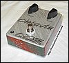
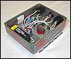
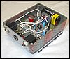
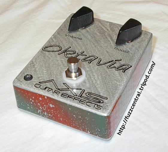
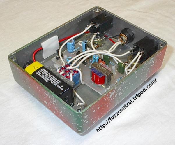
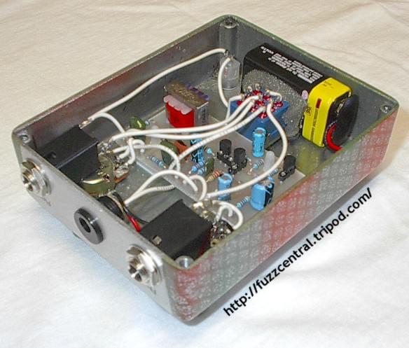
Here are some pictures of my Tycobrahe Octavia Clone. Click the thumbnails for the
full-size image! Use your browser's "Back" button to return to this page.
|
|
|
|
Note: These files are NOT to be used in a pedal that you are building for profit. The PCB file is
copyrighted artwork and is subject to a licensing fee.
Tycobrahe Octavia PCB
|
Here
|
Tycobrahe Octavia Layout
|
Here
|
Tycobrahe Octavia Parts List
|
Here
|
Build Difficulty: Moderate
|

|
|
The layout that I've included for this project is for the original positive ground version. To build it
as the negative ground version that I cooked up, replace the MPSA18 transistor with a 2N5087, and replace the two 2N6519 (or 2N3906) with
a pair of 2N4401. Then you'll need to reverse all the electrolytic capacitors. You DO NOT need to reverse the two 1N34A
Germanium diodes on the circuit's output.
|
|
|
| |
|
|
|
